
One thing I get asked about is point control, and I've a bit of a bone to chew on where that subject is concerned.
The first step is to read Brian Lambert's excellent guide. Find the section on point control and study it carefully. There is no substitute for reading this carefully:
https://www.brian-lambert.co.uk/Electrical_Page_1.html
https://www.brian-lambert.co.uk/Electrical_Page_2.html
https://www.brian-lambert.co.uk/Electrical_Page_3.html
Points motors and moving them
He takes you through the basics of using the Peco point motor (essentially two coils to produce a magnetic force to move the point across). There's a variety of methods shown for how to operate the coils - probe and stud from an A/C supply, then onto using CDUs on either probe and stud or push buttons, etc, which are both good options.
Then the next step is using an on/off switch, single wire, single capacitor, and a pair of diodes - all very effective and simple but it needs a decent power supply to drive it properly. All good so far.
Now if you're using electrofrog points and/or don't want to rely on the point blades for switching, then you're probably using a Peco auxiliary switch which is stuck onto the bottom of the points motor. In basic terms it's a sliding contact on a section of PCB - much like the sliding switch on a Seep-branded solenoid motor. Sliding contacts which are exposed to the atmosphere don't last long before the emergence takes place of high contact resistances due to dirt and oxidisation, and this plays havoc with running trains over the point, etc.
It also requires some of the available force to move the point across, which can result in a misfire. (If you have had to clean the point blades then you'll already know what I mean - if you've not cleaned them yet you'll have to at some time!) There are also the Peco 'micro switches' which are commonly used for double slips. These are better but, as they are also open to the elements (even if those elements are in a centrally-heated room in your house), again you can suffer high resistances. So, ideally, we want to replace this with something better. Hold onto that thought.
Controls
Now, thinking about your control panel - its nice to be able to see which way your points are set - you can't get this without extra circuitry for the probe and stud method. That just leaves Brian Lambert's switch and capacitor and diode method. Use a rotary switch and it does just that - shows you where the points are set. In addition, you could attach to this a relay to manage the frog polarity, which will work just fine. (But remember that this needs a decent power supply and is manual only. It cannot easily be automated.)
I've moved on a step further. The group known as MERG have developed a PD3 point driver - a very nice, professional bit of kit using a lot more parts - which controls the point from a single switch. This means that your control panel reflects the exact position of the points. It also has sufficient contacts for the frog polarity too. The only downside is you have to be a member of MERG to be able to buy the kit, which is a bit of a shame as it's reasonably priced.
Then a circuit appeared on the N Gauge Forum (see the Links page), which performs the same function as the MERG PD3 but with a lot less parts and is an easy DIY build.
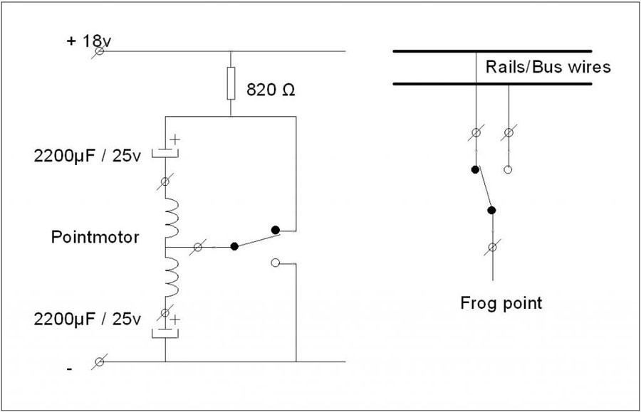
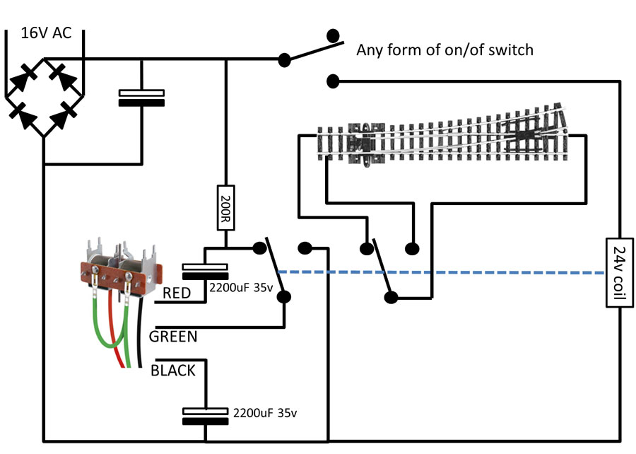
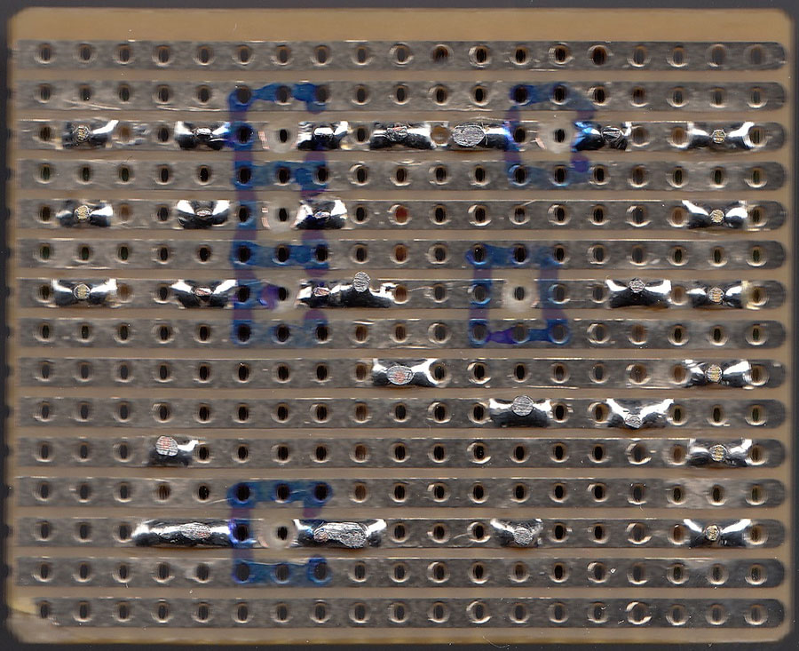
It works just as well with smaller power supplies as it does with bigger ones. It's what I've fitted to all of Bridgebury's points (with only one small adjustment to a resistor value), shown below:
Like the MERG PD3 and Brian's single wire method, there is one common disadvantage - when you power up your layout the points may not be in the state shown by the switch.
Don't worry! It's easy to deal with! Switch each point over and back. This lines up the point with the switch and it stays that way until you switch your layout off again. It's not much of a hardship to do this at the start of every operating session as it also shows you that each of your points is working.
So that's the Peco aux switch gone, a switch added to the panel that reflects the position of the point, and the frog polarity is more reliable.
Under operational circumstances, the point reflects the position of the switch. With a bit of forethought you can have the point set to whichever direction you want with the point switched off (call this the 'normal' direction for the point if that helps).
Installation
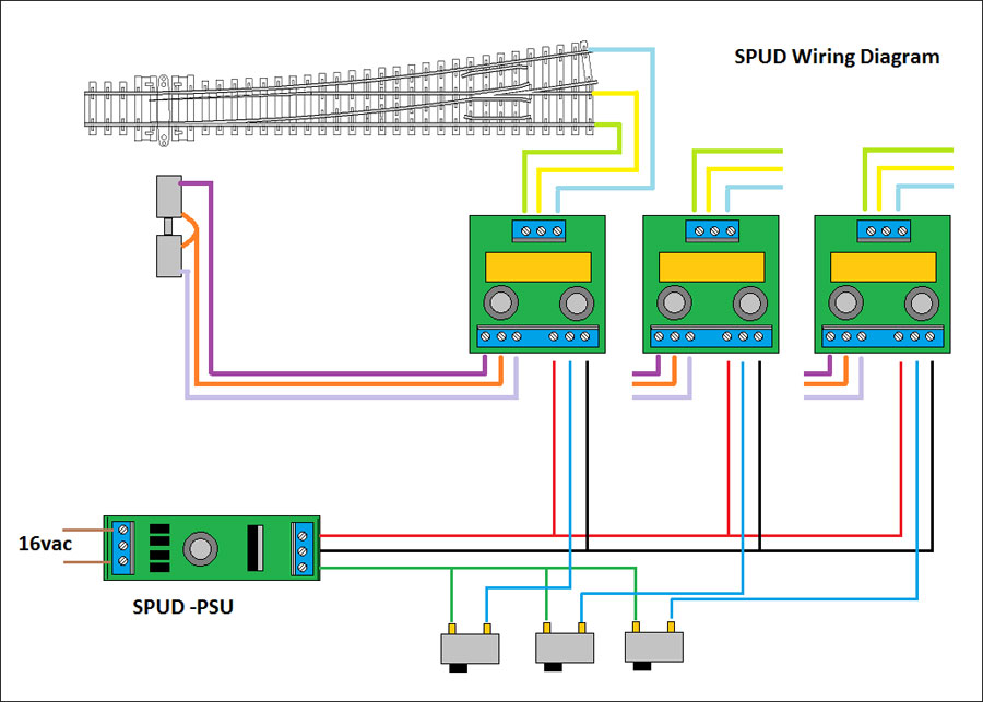
Arrange the switch on the panel so its how you want it - on or off for that particular direction. (Do not use momentary switches - only on/off switches.)
Wire it up to the point relay and try it out. If the point switches the opposite way to what you require then reverse the red and black wires to the solenoid and re-test.
You should now have the point working the way you want it. The next step is to connect the frog and running rail wires. If you get a short circuit on the track then reverse the running rail wires and re-test.
That's how complicated it isn't.
From there it is a very simple step to add basic route setting (or slave points together). Add a diode to operate each point you want to operate from a single switch to give you that route (or connect the wires from two or more points to one switch when slaving). The point is simply on/off controlled - now that's simple.
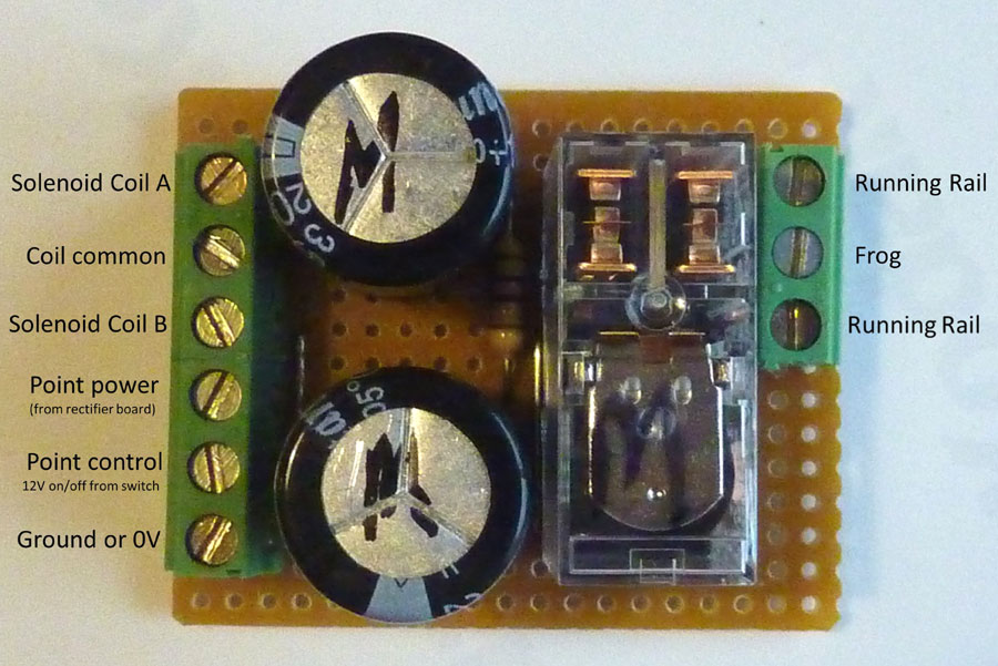
'Oh that's expensive', you say. Nope! A Peco aux switch is around £2.50. A small section of stripboard, one relay, one resistor, and two capacitors cost about the same on eBay.
The Advantages
- Relays are less prone to high contact resistances than the aux switch
- Each point effectively has its own CDU - you can operate as many points as fast as you like and they will keep up with you
- Can be driven from switches or any form of automation - it's simple on/off control
- Additional relays can be added to this system to control signals, etc
- No probe wire hanging around
- Switches show which way your points are facing
- Works on single slips, double slips, and any form of solenoid point motor
- Only control signals travel to the point - the high current spike which operates the point is entirely local to the point. You can use 7/0.2 wire to the point with no problem at all
Disadvantages
- Slightly more complex to install - its your choice!
- As it causes a momentary short on the rails it's not suitable for DCC without more tinkering (when the relay operates to fire the point the momentary short will trip your DCC)
- You cannot use one of these relays to do two points - each point must have its own relay (unless you dispense with the frog polarity side of things)
- Isn't slow and realistic in the way that servos might be, or hand controlled (wire-in-tube)
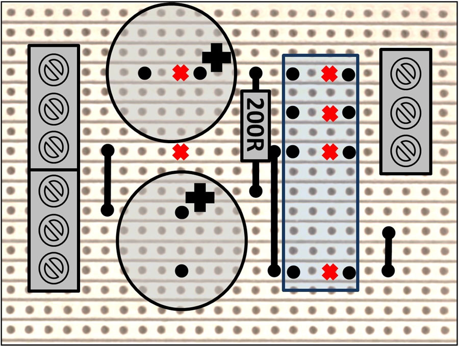
Please note: the red X marks a cut in the stripboard track (anything that cuts the track creates and electrical break). The black + denotes the polarity for the capacitors.
Failure to deal with either correctly results in melting or popping! The resistor can be any value between 200P and 820R - the lower the value, the faster the recharge speed. Capacitors are 2200uF 35V-rated for this '20V' version. Instead, you could have a separate, higher voltage power supply, in which case reduce the value of the capacitors. I use 1000uF 50V-rated on a 40V supply.
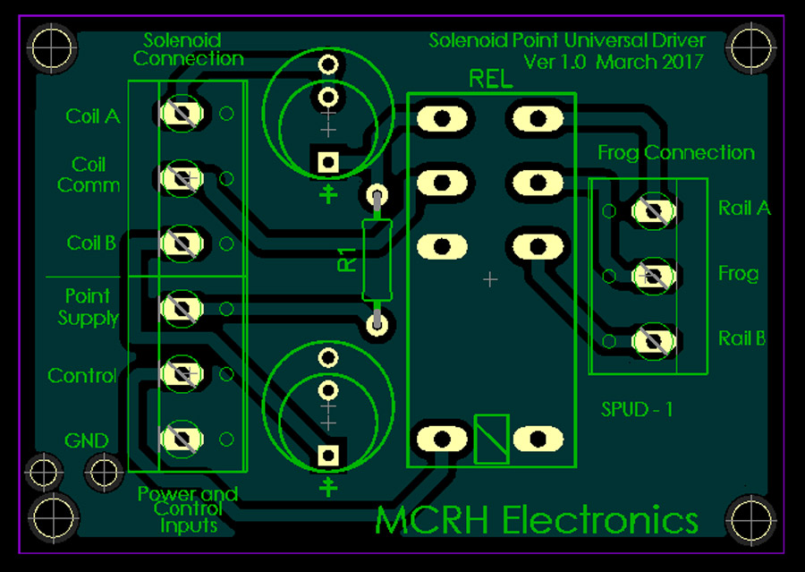
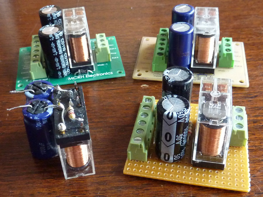
The stripboard design has been developed into a printed circuit board by MalcC.
http://micro-heli.co.uk/mcrh/index.htm
I've received my first batch of boards and have even got the missus to test-build one in twenty minutes (not bad, as she hasn't soldered before). In essence anyone can now do this.
Building and installing your boards is now very very simple!